Sorry for the "tech-talk", this page is intended for fellow amp builders.
Last updated 08/09/2006.
This reverb project is based on Ted Weber's version of the
1963 Fender 6G15 tube reverb unit.
I call my version the "Surfverb". It's kind of an obvious name for a spring reverb, so I'm sure someone else has already used it.
I'm also making a few modifications myself (hopefully it will still work):
I'm omitting the in/out foot switch - Why would I ever want to turn it off?
Just in case I come up with a reason to turn it off, I'm adding a front panel "true bypass" switch.
Added a "Standby" switch.
I put the power supply and audio circuits on separate boards. I was originally going to put them in separate chassis, but later
changed my mind because the cabinet would be too big. When I went shopping for a chassis, I couldn't find one that would hold both boards
so I ended up with two chassis anyway, only bolted end to end. Had I stuck to the original layout, including putting some of the components
on the pots, I could have used a smaller chassis.
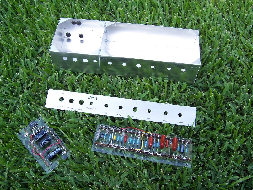
This is the chassis (actually two chassis bolted end to end). I have most of the holes drilled out.
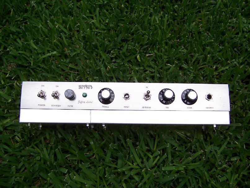
I made the face plate out of a flat aluminum bar (clamped to the chassis when drilling the chassis holes). I used computer decal paper to make the labels,
and sprayed it with clear paint (a "silver face" reverb?).
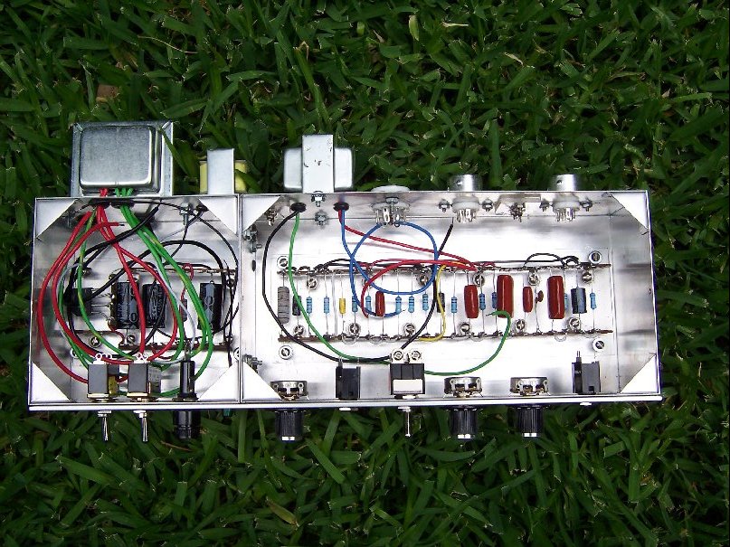
The circuit boards are made of terminal strips mounted on pieces of plexiglass (a "plexi" reverb?).
The beautiful lawn is Saint Augustine
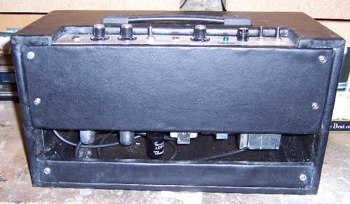
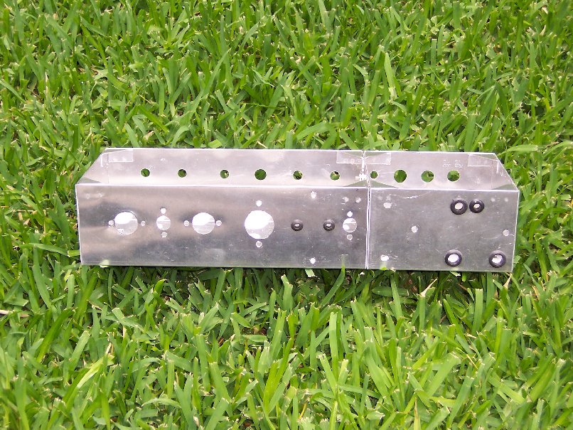
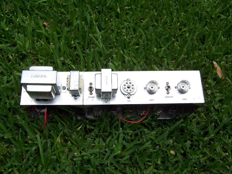
Here's the back of the chassis with the rest of the holes drilled and filed.
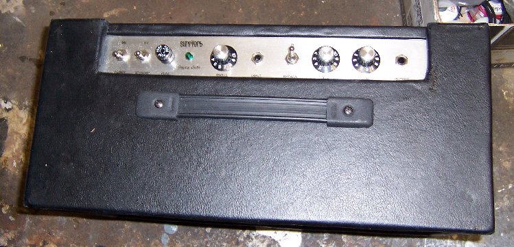
Here, all the parts are mounted to the chassis.
The back -
And the front -
At this point, I wired the power supply board to the power cord and other chassis mounted components, and fired it up for a power supply test.
The pilot light came on, and all the voltage measurements were good.
I did, however forget to unplug it, and the next day while routing wires for the tube heaters, I had my left hand on the grounded chassis, and my
right wrist touched a hot a/c power line connection... Don't try this at home!!!
I had hoped to have the preamp wired and tested by now, but a couple of things came up.
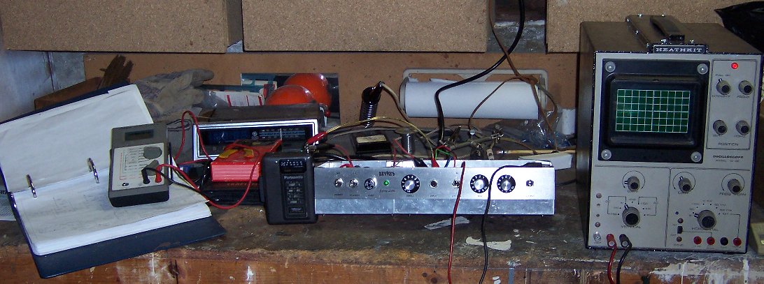
1. I thought my old Heathkit scope might come in handy for testing. I hadn't used it in about 20 years, and when I dug it out,
it was covered with corrosion, and one of the a/c plug prongs had rusted off. I was amazed to find that it still worked, so I took some time to
clean it up.
2. When I went to connect a wire from the circuit board to a tube socket, I realized I'd made a major blunder. I'd wired the board upside down, so that
all the tube connections were on the control side of the board, and all the control connections were on the tube side of the board. All the wires would have to
cross the board, making it look messy, and the wires would probably have been too long.
I had to remove all the wiring on the board, reverse the cathode electrolytic bypass caps, and rewire the board.
I've got the 1st preamp stage wired, and it appears to work!
Here it is on the bench getting a crude test. I don't have any kind of audio generator, so I hooked up the output of a radio/tape player to the
reverb input. The scope trace was much larger coming out of the 12AT7 tube than going in, and that's what an amplifier should do
Next I'll wire the 2nd gain stage which uses the other half of the same 12AT7 tube.
And yes, I remembered to unplug it when I was done And for those of you concerned, I've monitored the high voltage at the filter caps, and it falls to safe levels shortly after
powering down
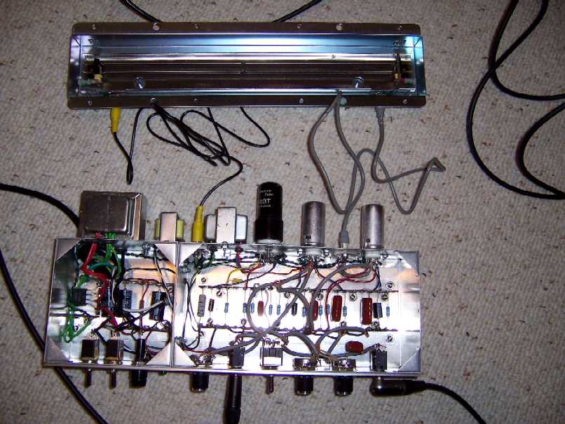
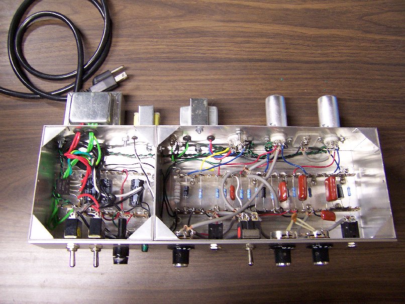
Here's another picture after a couple days of proceeding at a snail's pace:
I don't know if all the shielded cable is necessary, I'd just rather be safe than sorry.
Also, my decision to have only one chassis ground connection has added a lot to the wiring.
Here's what I did in the past couple of days:
1. Modified the board again - I decided to put the tone caps on the pots after all, it reduced some of the wiring.
2. Repositioned a few parts - due to my inexperience, some parts on my oversized board did not line up well with the tubes to which they were connnected.
3. Wired and tested the 2nd gain stage. I came up with another crude test for this. I wired an extra guitar pickup I had to the input. When I struck a
tuning fork, and placed it near the pickup, I could see the sine waves it generated at the various levels of amplification on my scope. Of course the pickup
picked up other noise in the area, so it wasn't perfect (I've got to build a cheap function generator).
4. Wired and tested the reverb recovery amp.
5. Wired the reverb driver stage.
I'm planning to run a test by connecting a guitar speaker to the reverb transformer. It should function as a single ended guitar amp. If that test
works, I only have to make a few more connections to complete the electronics phase of this project.
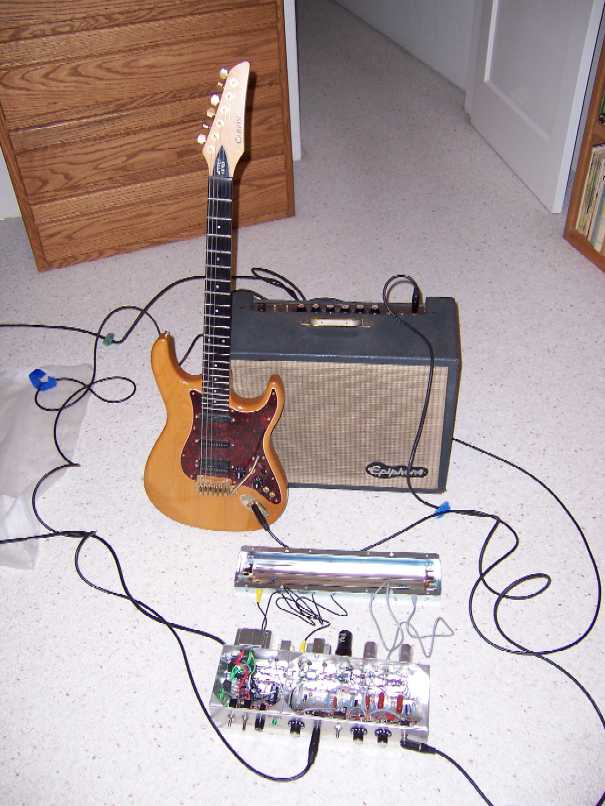
I tried out what I had so far, with a 12" Jensen guitar speaker in place of the reverb pan, and it worked. Then I wired the last few connections,
brought the chassis and the reverb pan into the "studio" and gave it the ultimate test:
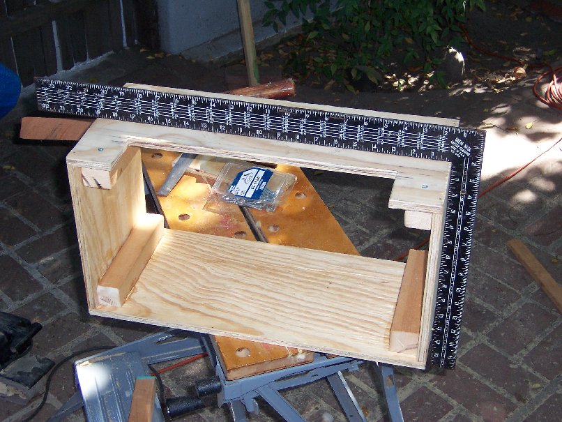
Good thing I didn't make a living at woodworking... It took me all day to go from raw materials to this much of the cabinet.
I was considering making it out of a nice grained hardwood, but decided that I didn't have the skills or tools to do it right,
so I decided to take the vinyl covered plywood route. I figured I could correct mistakes with Fix-All, and cover them with vinyl.
The only mistake I've caught so far, was that at first, I make the cut out for the control panel too small. Usually I make mistakes that
are not so easily corrected. It's a lot easier to take away more wood, than to add wood
Much to my delight and amazement, I was able to get the cabinet square.
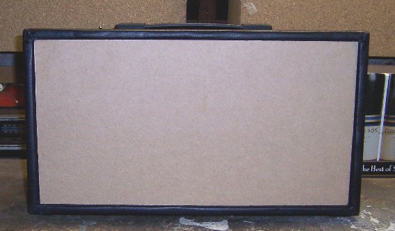
I'm almost done. All that's left is deciding what to do with the front panel.
Due to my limited cabinet making and upholstering skills, it already has a vintage road worn look. If I do another project like this, I would use a spray adhesive. I used white glue which was messy, and in some areas I used a hot glue gun
which made some lumps under the surface.
Back
Due to the angle of this top picture, it appears that the labels are covered, but they are not.
Problems And Fixes
The reverb sounded fine at bedroom volume, but when I cranked up the amp at a band practice, there was an annoying hum.
I found there were actually 5 factors contributing to the hum, the most severe masking the lower level hums. So finding the causes was like
pealing the layers of an onion.
The loudest hum was caused by a bad soldier joint. As I mentioned, I have only one connection to the chassis ground. The signal ground connections are sort
of "daisy chained" to each other sort of forming a ground bus. A bad connection was found in the "daisy chain" resulting in a poor connection to ground for
most of the circuit.
The next loudest hum was caused by my using a 3 wire a/c power chord, with the chassis grounded to the power chord ground wire. With the reverb plugged
into my amp, which also had it's chassis grounded to it's power chord ground wire, I had two ground connections between the reverb unit and the
guitar amp, causing a ground loop. I replaced the 3 wire a/c power chord with a 2 wire a/c power chord.
This left 3 much lower level hums.
I found that if the reverb pan came in contact with the chassis, there was a small hum. I suppose this was another ground loop. I fixed it by covering the
edge of the reverb pan that could come in contact with the chassis with electrical tape.
Another minor hum was cured by reversing the end to end orientation of the reverb pan within the cabinet, the slight hum went away when the output end of the
reverb pan was at the opposite end of the cabinet from the power transformer.
And lastly, there was a very minor hum that went away when I replaced the "no-name" 12AX7 tube with a brand name "Groove Tube".
The unit is real quite now!
I decided to go with a speaker grill front. Since I was using the grill material for my Speaker
Cab project, I ordered some extra for the front of the reverb.


 Don't try this at home!!!


 ).
).